
One thing I’ve learned a lot about in recent years is domain analysis and domain modeling. Every once in a while, an isolated piece of code or a separable concept shows me just how much I’ve missed out all the years before. A few weeks ago, I came across such an example and want to share the experience and insight. It’s a story about domain exploration with heightened degree of difficulty – another programmer had analyzed it before and written code that I should replace. But first, let’s talk about the domain.
The domain
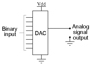 The project consisted of a machine control software that receives commands and alters the state of a complex electronic circuitry accordingly. The circuitry consists of several digital-to-analog converters (DAC), among other parts. We will concentrate on the DACs in this story. In case you don’t know what a DAC is, let me explain. Imagine a little integrated circuit (IC), the black bug-like electronic parts on a circuit board. On one side, you provide it a digital number in binary representation and on the other side, you’ll get an analog voltage that represents your number. Let’s say you drive a 8-bit DAC and give it a digital zero, the output will be zero volt. If you give the same DAC the number 255, it will output the maximum possible voltage. This voltage is given by the “reference voltage” pin and is usually tied to 5 V in traditional TTL logic circuits. If you drive a 12-bit DAC, the zero will still yield 0 V, while the 255 will now only yield about 0,3 V because the maximum digital number is now 4095. So the resolution of a DAC, given in bits, is a big deal for the driver.
 How exactly you have to provide that digital number, what additional signals need to be set or cleared to really get the analog voltage is up to the specific type of DAC. So this is the part of behaviour that should be encapsulated inside a DAC class. The rest of the software should only be able to change the digital number using a method on a particular DAC object. That’s our modeling task.
The original implementation
My job was not to develop the machine control software from scratch, but re-engineer it from existing sources. The code is written in plain C by an electronics technician, and it really shows. For our DAC driver, there was a function that took one argument – an integer value that will be written to the DAC. If the client code was lazy enough to not check the bounds of the DAC, you would see all kinds of overflow effects. It worked, but only if the client code knew about the resolution of the DAC and checked the bounds. One task the machine control software needed to do was to translate the command parameters that were given in millivolts to the correct integer number to feed it into the DAC and receive the desired millivolts at the analog output pin. This calculation, albeit not very complicated, was duplicated all over the place.
writeDAC(int value);
My original translation
One primary aspect when doing re-engineering work is not to assume too much and don’t change too many places at once. So my first translation was a method on the DAC objects requiring the exact integer value that should be written. The method would internally check for the valid value range because the object knows about the DAC resolution, while the client code should subsequently lose this knowledge. The original code translated nicely to this new structure and worked correctly, but I wasn’t happy with it. To provide the correct integer value, the client code needs to know about the DAC resolution and perform the calculation from millivolts to DAC value. Even if you centralize the calculation, there are still calls from everywhere to it.
dac.write(int value);
My first relevation
When I finally had translated all existing code, I knew that every single call to the DAC got their parameter in millivolts, but needed to set the DAC integer. Now I knew that the client code never cared about DAC integers at all, it cared about millivolts. If you find such a revelation, act on it – even just to see where it might lead you to. I acted and replaced the integer parameter of the write method on the DAC object with a voltage parameter. I created the Voltage domain type and had it expose factory methods to be easily created from millivolts that were represented by integers in the commands that the machine control software received. Now the client code only needed to create a Voltage object and pass it to the DAC to have that voltage show up at the analog output pin. The whole calculation and checking part happened inside the DAC object, where it belongs.
dac.write(Voltage required);
This version of the code was easy to read, easy to reason about and worked like a charm. It went into production and could be the end of the story.
The second insight
But the customer had other plans. He replaced parts of the original circuitry and upgraded most of the DACs on the way. Now there was only one type of DAC, but with additional amplifier functionality for some output pins (a typical DAC has several output pins that can be controlled by a pin address that is provided alongside the digital number). The code needed to drive the DACs, that were bound to 5 V reference voltage, but some channels would be amplified to double the voltage, providing a voltage range from 0 V to 10 V. If you want to set one of those channels to 5 V output voltage, you need to write half the maximum number to it. If the DAC has 12-bit resolution, you need to write 2047 (or 2048, depending on your rounding strategy) to it. Writing 4095 would yield 10 V on those channels.
Because the amplification isn’t part of the DAC itself, the DAC code shouldn’t know about it. This knowledge should be placed in a wrapper layer around the DAC objects, taking the voltage parameters from the client code and changing it according to the amplification of the channel. The client code would want to write 10 V, pass it to the wrapper layer that knows about the amplification and reduces it to 5 V, passing this to the DAC object that transforms it to the maximum reference voltage (5 V) that subsequently gets amplified to 10 V. This sounded so weird that I decided to review my domain analysis.
It dawned on me that the DAC domain never really cared about millivolts or voltages. Sure, the output will be a specific voltage, but it will be relative to your input in relation to the maximum value. The output voltage has the same percentage of the maximum value as the input value. It’s all about ratios. The DAC should always demand a percentage from the client code, not a voltage. This way, you can actually give it the ratio of anything and it will express this ratio as a voltage compared to the reference voltage. The DAC is defined by its core characteristics and the wrapper layer performs the translation from required voltage to percentage. In case of amplification, it is accounted for in this translation – the DAC never needs to know.
dac.write(Percentage required);
Expressiveness of the new concept
Now we can really describe in code what actually happens: A command arrives, requiring us to set a DAC channel to 8 volt. We create the voltage object for 8 volt and pass it on to the DAC wrapper layer. The layer knows about the 2x amplification and the reference voltage. It calculates that 8 volt will be 80% of the maximum DAC value (80% of 5 V being 4 V before and 8 V after amplification) and passes this information to the DAC object. The DAC object, being the only one to know its resolution, sets 0.8 * maximum_DAC_value to the required register and everything works.
The new concept of percentages decouples the voltage information from the DAC resolution information and keeps both informations where they belong. In fact, the DAC chip never really knows about the reference voltage, either – it’s the circuit around it that knows.
Conclusion
While it is easy to see why the first version with voltages as parameters has its charms, it isn’t modeling the reality accurately and therefor falls short when flexibility is required. The first version ties DAC resolution and reference voltage together when in fact the DAC chip only knows the resolution. You can operate the chip with any reference voltage within a valid range. By decoupling those informations and moving the knowledge about reference voltages outside the DAC object, I modeled the reality more accurate and every requirement finds its natural place. This “natural place finding” is what makes a good model useful for reasoning. In our case, the natural place for the reference voltage was outside the DAC in the wrapper layer. Finding a real name for the wrapper layer was easy, I called it “circuit board”.
Domain analysis is all about having the right abstractions for your model. Your model is suitable for your task when everything fits and falls into place nearly automatically. When names needn’t be found but kind of obtrude themselves from the real domain. The right model (for the given task) feels good and transports a lot of domain knowledge. And domain knowledge is the most treasurable knowledge for any developer.
