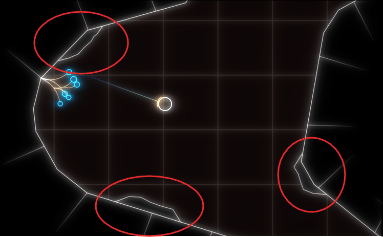
Simple marching squares in C++

Marching squares is an algorithm to find the contour of a scalar field. For example, that can be a height-map and the resulting contour would be lines of a specific height known as ‘isolines’.

At the core of the algorithm is a lookup table that says which line segments to generate for a specific ’tile’ configuration. To make sense of that, you start with a convention on how your tile configuration and the resulting lines are encoded. I typically add a small piece of ASCII are to explain that:

// c3-e3-c2
// |      |
// e0    e2
// |      |
// c0-e1-c1
//
// c are corner bits, e the edge indices

The input of our lookup table is a bitmask of which of the corners c are ‘in’ or above our isolevel. The output is which tile edges e to connect with line segments. That is either 0, 1 or 2 line segments, so we need to encode that many pairs. You could easily pack that into a 32-bit, but I am using a std::vector<std::uint8_t> for simplicity. Here’s the whole thing:

using config = std::vector<std::uint8_t>;
using config_lookup = std::array<config, 16>;
const config_lookup LOOKUP{
  config{},
  { 0, 1 },
  { 1, 2 },
  { 0, 2 },
  { 2, 3 },
  { 0, 1, 2, 3 },
  { 1, 3 },
  { 0, 3 },
  { 3, 0 },
  { 3, 1 },
  { 1, 2, 3, 0 },
  { 3, 2 },
  { 2, 0 },
  { 2, 1 },
  { 1, 0 },
  config{},
};

I usually want to generate index meshes, so I can easily connect edges later without comparing the floating-point coordinates. So one design goal here was to generate each point only once. Here is the top-level algorithm:

using point_id = std::tuple<int, int, bool>;

std::vector<v2<float>> points;
// Maps construction parameters to existing entries in points
std::unordered_map<point_id, std::uint16_t, key_hash> point_cache;
// Index pairs for the constructed edges
std::vector<std::uint16_t> edges;

auto [ex, ey] = map.size();
auto hx = ex-1;
auto hy = ey-1;

// Construct inner edges
for (int cy = 0; cy < hy; ++cy)
for (int cx = 0; cx < hx; ++cx)
{
  std::uint32_t key = 0;
  if (map(cx, cy) > threshold)
    key |= 1;
  if (map(cx + 1, cy) > threshold)
    key |= 2;
  if (map(cx + 1, cy + 1) > threshold)
    key |= 4;
  if (map(cx, cy + 1) > threshold)
    key |= 8;

  auto const& geometry = LOOKUP[key];

  for (auto each : geometry)
  {
    auto normalized_id = normalize_point(cx, cy, each);
    auto found = point_cache.find(normalized_id);
    if (found != point_cache.end())
    {
      edges.push_back(found->second);
    }
    else
    {
      auto index = static_cast<std::uint16_t>(points.size());
      points.push_back(build_point(map, threshold, normalized_id));
      edges.push_back(index);
      point_cache.insert({ normalized_id, index });
    }
  }
}

For each tile, we first figure out the lookup input-key by testing the 4 corners. We then get-or-create the global point for each edge point from the lookup.
Since each edge in a tile can be accessed from two sides, we first normalize it to have a unique key for our cache:

point_id normalize_point(int cx, int cy, std::uint8_t edge)
{
  switch (edge)
  {
  case 3:
    return { cx, cy + 1, false };
  case 2:
    return { cx + 1, cy, true };
  default:
    return { cx, cy, edge == 0 };
  };
}

When we need to create a point an edge, we interpolate to estimate where exactly the isoline intersects our tile-edge:

v2<float> build_point(raster_adaptor const& map, float threshold, point_id const& p)
{
  auto [x0, y0, vertical] = p;
  int x1 = x0, y1 = y0;
  if (vertical)
    y1++;
  else
    x1++;

  const auto s = map.scale();
  float h0 = map(x0, y0);
  float h1 = map(x1, y1);
  float lambda = (threshold - h0) / (h1 - h0);

  auto result = v2{ x0 * s, y0 * s };
  auto shift = lambda * s;
  if (vertical)
    result[1] += shift;
  else
    result[0] += shift;
  return result;
}

For a height-map, that’s about as good as you can get.

You can, however, sample other scalar field functions with this as well, for example sums of distances. This is not the most sophisticated implementation of marching squares, but it is reasonably simple and can easily be adapted to your needs.

Unveiling the secrets of invisible database columns

After my last blog post, where I wrote about Generated and Virtual Columns, I would like to dedicate this post to another type of database column: Invisible Columns. This feature exists in MySQL since version 8.0 and in Oracle Database since version 12c. PostgreSQL and MS SQL Server do not support this feature.

Invisible columns, as the name suggests, are columns within a table that are hidden from standard query results by default. Unlike traditional columns that are visible and accessible in query results, invisible columns are not included unless explicitly specified in the query.

This feature provides a level of control over data visibility, allowing developers to hide certain columns from applications or other database users while still retaining their functionality within the database.

Defining invisible columns

When creating a table in MySQL or Oracle, you can designate certain columns as invisible by using the INVISIBLE keyword in the column definition. For example:

CREATE TABLE your_table (
  visible_column   INT,
  invisible_column INT INVISIBLE
);

In this example, the invisible_column is marked as invisible, while the visible_column remains visible by default. To alter an existing table and make a column invisible:

ALTER TABLE your_table
  MODIFY COLUMN existing_column_name INVISIBLE;

Replace your_table with the name of your table and existing_column_name with the name of the column you want to make invisible.

When querying the your_table, the invisible column will not be included in the result set unless explicitly specified:

SELECT * FROM your_table;

visible_column
--------------
   4
   8
  15

By default, invisible columns are hidden from query results, providing a cleaner and more concise view of the data. However, developers can still access invisible columns when needed by explicitly including them in the query:

SELECT visible_column, invisible_column FROM your_table;

visible_column | invisible_column
---------------------------------
   4           |   16
   8           |   23
  15           |   42
Unveiling invisible columns

To list the invisible columns of a table in MySQL, you can query the information_schema.columns system table and filter the results based on the COLUMN_DEFAULT column. Invisible columns have NULL as their default value. Here’s a simple SQL query to accomplish this:

SELECT COLUMN_NAME
  FROM information_schema.columns
  WHERE TABLE_SCHEMA = 'your_database'
    AND TABLE_NAME = 'your_table'
    AND COLUMN_DEFAULT IS NULL;

In Oracle, you can query the USER_TAB_COLUMNS or ALL_TAB_COLUMNS data dictionary views to list the invisible columns of a table. Here’s how you can do it:

SELECT COLUMN_NAME
  FROM USER_TAB_COLUMNS
  WHERE TABLE_NAME = 'your_table'
    AND INVISIBLE = 'YES';

If you want to list invisible columns from all tables in the current schema, you can use the ALL_TAB_COLUMNS view instead:

SELECT TABLE_NAME, COLUMN_NAME
  FROM ALL_TAB_COLUMNS
  WHERE INVISIBLE = 'YES';
Are invisible columns actually useful?

Invisible columns can make schema evolution easier by providing a flexible mechanism for evolving database schemas over time without disrupting existing applications or queries. You can test new features or data structures without committing to them fully. Invisible columns provide a way to add experimental columns to your tables without exposing them to production environments until they are fully tested and ready for use.

They can create cleaner and more concise views of your data by hiding less relevant columns. This can make it easier for developers, analysts, and users to work with the data without unnecessary clutter. However, I would argue that this is also achievable with normal database views.

The downside of introducing invisible columns is that they add complexity to the database schema, which can make it harder to understand and maintain, especially for developers who are not familiar with the invisible columns feature. They also add potential for confusion: Developers may forget about the presence of invisible columns, leading to unexpected behavior in queries or applications.

You probably shouldn’t use them to hide sensitive data, since invisible columns don’t have any additional access control, and security through obscurity is not a good idea. If you grant SELECT permission on the table to a user, they will be able to query visible and invisible columns alike.

Now that you know about them, you can make your own choice.

When open source is only marketing

Nowadays, Open Source Software (OSS) is everywhere and probably everyone is using it somewhere. It may be your browser, the operating system on your phone, some libraries of your beloved games and apps or some web server software or infrastructure software delivering websites and other data like music or videos to you. Basically, OSS is everywhere – even if it is sometimes not openly visible.

When developing software we often use libraries and frameworks that are open source. For us it is great for a couple of reasons:

  • Often free of cost
  • We can have a look under the hood to learn how something is done
  • We can check and review the code for security issues to increase trust
  • We can improve the software, adapt it to our use case or fix issues plaguing us

In using OSS and probably contributing to it by either feedback or code we strenghen the software development community and are pushing our domain a little forward step-by-step.

Some companies noticed the positive notion about OSS and started to build their businesses on OSS. They pay developers to develop or contribute to OSS and provide services around it offering assistance, support or solutions based on their OSS. Companies like Red Hat or Nextcloud have quite some success with this model.

I personally think it is a great way of business leading to a win-win situation in the IT world: A company can make money and millions of other developers can increase their productivity or develop their own solutions standing on the shoulder of giants (aka OSS).

Open Source done wrong

Sometimes, I feel open source is only used as a label and marketing tool. Let me illustrate by an example I stumbled upon a few weeks ago:

There is an OSS javascript library with a github repository, issue tracker and so on. Sounds like a proper open source project, doesn’t it?

Well, there is an issue or maybe more a lacking feature that some people noticed and somebody even opened a pull request with a proposed fix.

The fix does not breaking anything, consists of the addition of 5 lines in one file and some CSS styles in another and only adds a feature to one component of the library.

Still, the pull request (PR) was simply put down and closed with a comment along the lines

“We do not think this is necessary, so we do not accept it.”

A follow-up issue 3 (!) years later was closed with a copy&paste comment, too.

While of course it is always the right and obligation (look at the recent supply chain attacks!) of the maintainers to decide what gets in and what does not it sometimes just has the notion of “No, not invented here”. Blocking unobstrusive, small and sensible changes without real reasons is very counter-productive. It defeats some of the main advantages of an open source solution:

Developers are not able to give back and get their improvements upstream. This leads to workarounds, forks oder separately maintained patches. That in turn means overhead and more overall effort needed to build and maintain a solution thus mitigating part of the benefits using the OSS in the first place.

Do not take me wrong: Closed/proprietary software does not even give you many of the options and advantages of OSS. It offers more of a “take it as it is” approach and leaves it up to you to decide if it is worth it or not.

Doing it right

On the other hand there are tons of well governed open source projects that really consider contributions for upstream and listen to the community. We have had several successful contributions to the Tango and Grails projects for example.

So if you or your company run an open source project I advise you to be open and to listen to your users. Working as a loosely connected distributed team with a good steering team at the helm leads to many potential win-win situations and makes the (software development) world a better place.

Separation of Intent and Implementation

Last week, my colleague wrote about building blocks and how to achieve a higher-level language in your code by using them. Instead of talking about strings and files, you change your terms to things like coordinates and resources.

I want to elaborate on one aspect of this improvement, that aims at the separation of your intent from the current implementation. Your intent is what you want to achieve with the code you write. The current implementation is how you achieve it right now. I point out the transience of the implementation so clearly because it is most likely the first (and maybe even only) thing to change.

I have an example of this concept that is hopefully understandable enough. Let’s say that you build a system that gathers a lot of environmental data and stores it for later analysis and introspection. Don’t worry, the data consists mostly of things like air pressure, temperature and radioactive load. Totally harmless stuff – unless you find the wrong isotopes. In that case, you want to have a closer look and understand the situation. Most temporarily increased radioactivity in the air is caused by a normal thunderstorm. Most temporarily decreased radioactivity in the air is caused by a normal rain.

Storing all the data requires something like an archive. We want to store the data separated by the point of measurement (a “station”), the type of data (let’s call it “data entry type” because we aren’t very creative with names here) and by the exact point in time the measurement took place. To make matters a little bit more complicated, we might have more than one device in a station that captures a specific data entry type. Think about two thermometers on both sides of the station to make local heatup effects visible.

In order to reference a definite entry in our archive, we need a value for four aspects or dimensions :

  • The station
  • The data entry type
  • The device
  • The date and time

Thinking from the computer

If you implement your archive in the file system, you can probably see the directory structure right before you:

And in each directory for the day, we have a file for each hour:

So we can just write a class that takes our four parameters and returns the corresponding file. That is a straighforward and correct implementation.

It is also one of the implementations that couples your intent (an archive with four dimensions of navigability) nearly inseparably with your decisions on how to use your computer’s basic resources.

Thinking from the algorithms point of view

In order to separate your intent from your current implementation, you need to specify your intent as unencumbered from details as possible. Let’s specify our 4-axis archive nagivation system as a coordinate:

public record ArchiveCoordinate(
    StationId station,
    DataEntryType type,
    DeviceId device,
    LocalDateTime measurementTime
) {
}

There is nothing in here that point towards file system things like directories or files. We might have a hunch of the actual hierarchy by looking at the order of the parameters, but it is easy to implement a hierarchy-free nagivation between coordinates:

public record ArchiveCoordinate([...]) {
    public ArchiveCoordinate withStationChangedTo(
        StationId newStation
    ) {
        [...]
    }
    
    public ArchiveCoordinate withTypeChangedTo(
        DataEntryType newType
    ) {
        [...]
    }
    
    public ArchiveCoordinate withDeviceChangedTo(
        DeviceId newDevice
    ) {
        [...]
    }
    
    public ArchiveCoordinate withMeasurementTimeChangedTo(
        LocalDateTime newMeasurementTime
    ) {
        [...]
    }
}

The concept is that if you know one coordinate, you can navigate relative to it through the archive, without knowingly changing the directory or whatever implementation structure lies beneath your model layer. Let’s say we have the coordinate of a particular measurement of one thermometer. How do we get the same measurement of the other thermometer?

ArchiveCoordinate measurementForThermometer0 = new ArchiveCoordinate([...]);
ArchiveCoordinate measurementForThermometer1 = measurementForThermometer0.withDeviceChangedTo(thermometer1);

We can provide methods that allow us to step forward and backward in time. We can provide our application code with everything it requires to implement clear and concise algorithms based on our model of the archive.

But there will be the moment where you want to “get real” and access the data. You might decide to let your current implementation shine through to your intent layer and provide an actual file:

public interface Archive {
    Optional<File> entryFor(ArchiveCoordinate coordinate);
}

That’s all you need from the archive to get your file. But you might also decide to prolong your intent layer and wrap the file in your own data type that provides everything your algorithms need without revealing that it is really a file that lies underneath:

public interface Archive {
    Optional<ArchiveResource> entryFor(ArchiveCoordinate coordinate);
}

The new ArchiveResource is a thin, but effective veneer (some might call it a wrapper or a facade) that gives us the required information:

public interface ArchiveResource {
    String name();
    long size();
    InputStream read();
}

Of course, we need to provide an implementation for all of this. But by staying vague in the intent layer, we open the door for an implementation that has nothing to do with files. Instead of a file system, there could be a relational database underneath and we wouldn’t notice. Our algorithms would still work the same way and read their data from ArchiveResources that aren’t FileArchiveResources anymore, but DatabaseArchiveResources.

You can probably imagine how you can provide the intent for data writing using the example above. If not, let me show you the necessary additions:

public interface Archive {
    Optional<ArchiveResource> entryFor(ArchiveCoordinate coordinate);
    ArchiveResource createEntryFor(ArchiveCoordinate coordinate) throws IOException;
}
public interface ArchiveResource {
    String name();
    long size();
    InputStream read();
    OutputStream write();
}

Now you can store additional data to the archive without ever knowing if you write to a file or a database or something completely different.

Summary

By separating your intent from your current actual implementation, you gain at least three things for the cost of more work and some harder thinking:

  1. Your algorithms only use your intent layer. You design it exclusively for your algorithms. It will fit like a glove.
  2. The terms you use in your intent layer shape the algorithm metaphors way better than the terms of your current implementation. You can freely decide what terms you’ll use.
  3. The algorithms and your intent layer are designed to last. Your current implementation can be swapped out without them noticing.

If this sounds familiar to you, it is a slightly different take on the “ports and adapters” architecture. The important thing is that by starting with the intent and naming it from the standpoint of your algorithms (application code), you are less prone to let your implementation shine through.

How building blocks can be a game changer for your project

I have just completed my first own project. In this project I have a web server whose main task is to load files and return them as a stream.
In the first version, there was a static handler for each file type, which loaded the file and sent it as a stream.

As part of a refactoring, I then built building blocks for various tasks and the handler changed fundamentally.

The initial code

Here you can see a part of my web server. It offers a path for both images and audio files. The real server has significantly more handlers and file types.

public class WebServer{
    public static void main(String[] args) {
        var app = Javalin.create()
            .get("api/audio/{root}/{path}/{number}", FileHandler::handleAudio)
            .get("api/img/{root}/{path}/{number}", FileHandler::handleImage)
            .start(7070);
    }
}

Below is a simplified illustration of the handlers. I have also shown the imports of the web server class and the web server technology, in this case Javalin. The imports are not complete. They are only intended to show these two dependencies.

import WebServer;
import io.javalin.http.Context;
// ...

public class FileHandler {

    public static void handleImage(Context ctx) throws IOException {
        var resource = Application.class.getClassLoader().getResourceAsStream(
            String.format(
                "file/%s/%s/%s.jpg", 
                ctx.pathParam("root"), 
                ctx.pathParam("path"), 
                ctx.pathParam("fileName")));
        String mimetyp= "image/jpg";

        if (resource != null) {
            ctx.writeSeekableStream(resource, mimetyp);
        }
    }

    public static void handleAudio(Context ctx) {
        var resource = Application.class.getClassLoader().getResourceAsStream(
            String.format(
                "file/%s/%s/%s.mp3", 
                ctx.pathParam("root"), 
                ctx.pathParam("path"), 
                ctx.pathParam("fileName")));
        String mimetyp= "audio/mp3";

        if (resource == null) {
            resource = Application.class.getClassLoader().getResourceAsStream(
            String.format(
                "file/%s/%s/%s.mp4", 
                ctx.pathParam("root"), 
                ctx.pathParam("path"), 
                ctx.pathParam("fileName")));
            mimetyp= "video/mp4";
        }

        if (resource != null) {
            ctx.writeSeekableStream(resource, mimetyp);
        }
    }
}

The handler methods each load the file and send it to the Javalin context. The audio handler first searches for an audio file and, if this is not available, for a video file. The duplication is easy to see. And with the static handler and Javalin dependencies, the code is not testable.

Refactoring

So first I build an interface, called a decorator, for the context to get the Javalin dependency out of the handlers. A nice bonus: I can manage the handling of not found files centrally. In the web server, I then inject the new WebContext instead of the Context.

public interface WebContext {
    String pathParameter(String key);
    void sendNotFound();
    void sendResourceAs(String type, InputStream resource);
    default void sendResourceAs(String type, Optional<InputStream> resource){
        if(resource.isEmpty()){
            sendNotFound();
            return;
        }
        sendResourceAs(type, resource.get());
    }
}

public class JavalinWebContext implements WebContext {
    private final Context context;

    public JavalinWebContext(Context context){
        this.context = context;
    }

    @Override
    public String pathParameter(String key) {
        return context.pathParam(key);
    }

    @Override
    public void sendNotFound() {
        context.status(HttpStatus.NOT_FOUND);
    }

    @Override
    public void sendResourceAs(String type, InputStream resource) {
        context.writeSeekableStream(resource, type);
    }
}

Then I write a method to load the file and send it as a stream.

private boolean sendResourceFor(String path, String mimetyp, Context context){
    var resource = Application.class.getClassLoader().getResourceAsStream(path);
    if (resource != null) {
        context.sendResourceAs(mimetyp, resource);
        return true;
    }
    return false;
}

The next step is to build a loader for the files, which I pass to the no longer static handler during initialization. Here I can run a quick check to see if anyone is trying to manipulate the specified path.

public class ResourceLoader {
    private final ClassLoader context;

    public ResourceLoader(ClassLoader context){
        this.context = context;
    }

    public Optional<InputStream> asStreamFrom(String path){
        if(path.contains("..")){
            return Optional.empty();
        }
        return Optional.ofNullable(this.context.getResourceAsStream(path));
    }
}

Finally, I build an extra class for the paths. The knowledge of where the files are located and how to determine the path from the context should not be duplicated everywhere.

public class FileCoordinate {
    private static final String FILE_CATEGORY = "file";
    private final String root;
    private final String path;
    private final String fileName;
    private final String extension;

    private FileCoordinate(String root, String path, String fileName, String extension){
        super();
        this.root = root;
        this.path = path;
        this.fileName = fileName;
        this.extension = extension;
    }

    private static FileCoordinate pathFromWebContext(WebContext context, String extension){
        return new FileCoordinate(
                context.pathParameter("root"),
                context.pathParameter("path"),
                context.pathParameter("fileName"),
                extension
        );
    }

    public static FileCoordinate toImageFile(WebContext context){
        return FileCoordinate.pathFromWebContext(context, "jpg");
    }

    public static FileCoordinate toAudioFile(WebContext context){
        return FileCoordinate.pathFromWebContext(context, "mp3");
    }

    public FileCoordinate asToVideoFile(){
        return new FileCoordinate(
                root,
                path,
                fileName,
                "mp4"
        );
    }

    public String asPath(){
        return String.format("%s/%s/%s/%s.%s", FILE_CATEGORY, root, path, fileName, extension);
    }
}

Result

My handler looks like this after refactoring:

public class FileHandler {
    private final ResourceLoader resource;

    public FileHandler(ResourceLoader resource){
        this.resource = resource;
    }

    public void handleImage(WebContext context) {
        var coordinate = FileCoordinate.toImageFile(context);
        sendResourceFor(coordinate, "image/jpg", context);     
    }

    public void handleAudio(WebContext context) {
        var coordinate = FileCoordinate.toAudioFile(context);
        var found = sendResourceFor(coordinate, "audio/mp3", context);
        if(!found)
            sendResourceFor(coordinate.asToVideoFile(), "video/mp4", context);
    }

    private boolean sendResourceFor(FileCoordinate coordinate, String mimetype, WebContext context){
        var stream = resource.asStreamFrom(coordinate);
        context.sendResourceAs(mimetype, stream);
        return stream.isPresent();
    }
}

It is much shorter, easier to read and describes more what is done and not how it is technically done. Another advantage is that I can, for example, fully test my FileCoordinate and mock my WebContext.

For just these two handler methods, it still looks like a overkill. Overall, more code has been created than has disappeared and yes, a smaller modification would probably have been sufficient for this handler alone. But my application is not just this handler and most of them are much more complex. For example, I work a lot with json files, which are loaded and which my loader can now simply interpret using an additional function that return a JsonNode instead a stream. The conversion has significantly reduced the complexity of the application, avoided duplications and made the code more secure and testable.

Web Components, Part 2: Encapsulating and Reusing common Element Structure

In my previous post, I gave you some first impressions about custom HTML Web Components. I cut myself short there to make my actual point, but one can surely extend this experiment.

The thing about the DOM is that it is one large, global block of information. In order to achieve loose coupling, you need to exert that discipline by yourself, using document.getElementById() and friends you can easily couple the furthestmost components, to their inner workings, together. Which can make it very insecure to change.

For that problem in Web Components, there is the Shadow DOM. I.e. if you define, as previously, your component as

class CustomIcon extends HTMLElement {
    connectedCallback() {
        this.innerHTML = `
            <svg id="icon">
                <!-- some content -->
            </div>
        `;
        element = document.getElementById("icon");
        element.addEventListener(...);
        // don't forget to removeEventListener(...) in disconnectedCallback()! - but that is not the point here
    }
}

it becomes possible to also document.getElementById("icon") from anywhere globally. Especially with such generic identifiers, you really do not want to leak your inner workings. (Yes, in a very custom application, there might be valid cases of desired behaviour, but then usually the IDs are named as e.g. __framework_global_timeout, custom--modal-dialog, … as to avoid accidental clashes).

This is done as easy as

class CustomIconim d extends HTMLElement {
    constructor() {
        super();
        this.attachShadow({ mode: 'open' });
  }

    connectedCallback() {
        this.shadowRoot.innerHTML = ... // your HTML ere
    }
}

Two points:

  • The attachShadow() can also be called in the connectedCallback(), even if usually not required. Generally, there is some debate between these two options, and I think I’ll write you another episode of this post when I have some further insight about that.
  • The {mode: 'open'} is what you actually use because ‘closed’ does not give you that much benefit, as outlined in this blog here. Just keep in mind that yes, it’s still JavaScript – you can access the shadowRoot object from the outside and then still do your shenanigans, but at least you can’t claim to have done so by accident.

This encapsulation makes it easier to write reusable code, i.e. decrease duplication.

As with my case of the MagicSparkles icon – I might want to implement some other (e.g. Font Awesome) icons and have all of these carry the same “size” attribute. It might look like:

export const addSvgPathAsShadow = (element: HTMLElement, { children, viewBox, defaultColor }: SvgIconProps) => {
    const shadow = element.attachShadow({ mode: "open" });
    const size = element.getAttribute("size") || 24;
    const color = defaultColor || "currentcolor";
    viewBox ||= `0 0 ${size} ${size}`;
    shadow.innerHTML = `
            <svg
                xmlns="http://www.w3.org/2000/svg"
                width="${size}"
                height="${size}"
                viewBox="${viewBox}"
                fill="${color}"
            >
                ${children}
            </svg>
        `;
};

export class PlayIcon extends HTMLElement {
    connectedCallback() {
        addSvgPathAsShadow(this, {
            viewBox: "0 0 24 24",
            children: "<path fill-rule=\"evenodd\" d=\"M4.5 5.653c0-1.427 1.529-2.33 2.779-1.643l11.54 6.347c1.295.712 1.295 2.573 0 3.286L7.28 19.99c-1.25.687-2.779-.217-2.779-1.643V5.653Z\" clip-rule=\"evenodd\" />"
        });
    }
}

// other elements can be defined similarly

// don't forget to actually define the element tag somewhere top-level, as with:
// customElements.define("play-icon", PlayIcon);

Note that

  • this way, children is required as a fixed string. My experiment didn’t work out yet how to use the "<slot></slot>" here (to pass the children given by e.g. <play-icon>Play!</play-icon>)
  • Also, I specifically use the || operator for the default values – not the ?? – as an attribute given as empty string would not be defaulted otherwise (?? only checks for undefined or null).
Conclusion

As concluded in my first post, we see that one tends to recreate the same patterns as already known from the existing frameworks, or software architecture in general. The tools are there to increase encapsulation, decrease coupling, decrease duplication, but there’s still no real reason why not just to use one of the frameworks.

There might be at some point, when framework fatigue is too much to bear, but try to decide wisely.

Four-way Navigation in UIs

Just yesterday, I was working on the task of enabling gamepad navigation of a graphical UI. I had implemented this before in my game abstractanks but since forgotten how exactly I did it. So I opened the old code and tried to decipher it, and I figured that’d make a nice topic to write about.

Basic implementation

Let’s break down the simple version of the problem: You have a bunch of rectangular controls, and given a specific one, figure out the next one with an input of either left, up, right or down.

This sketch shows a control setup with a possible solution. It also contains an interesting situation: going ‘down’ from B box goes to C, but going up from there goes to A!

The key to creating this solution is a metric that weights the gap for a specific input direction, e.g. neighbor_metric(
box<> const& from, box<> const& to, navigation_direction direction)
. To implement this, we need to convert this gap into numbers we can use. I’ve used a variant of Arvo’s algorithm for that: For both axes, get the difference of the rectangles’ intervals along that axis and store those in a 2d-vector. In code:

template <int axis> inline float difference_on_axis(
box<> const& from, box<> const& to)
{
if (to.min[axis] > from.max[axis])
return to.min[axis] - from.max[axis];
else if (to.max[axis] < from.min[axis])
return to.max[axis] - from.min[axis];
return 0.f;
}

v2<> arvo_vector(box<> const& from, box<> const& to)
{
return {
difference_on_axis<0>(from, to),
difference_on_axis<1>(from, to) };
}

That sketch shows the resulting vectors from the box in the top-left going to two other boxes. Note that these vectors are quite different from the difference of the boxes’ centers. In the case of the two top boxes, the vector connecting the centers would tilt down slightly, while this one is completely parallel to the x axis.

Now armed with this vector, let’s look at the metric I was using. It results in a 2d ‘score’ that is later compared lexicographically to determine the best candidate: the first number determines the ‘angle’ with the selected axis, the other one the distance.

template <int axis> auto metric_on_axis(box<> const& from, box<> const& to)
{
auto delta = arvo_vector(from, to);
delta[0] *= delta[0];
delta[1] *= delta[1];
auto square_distance = delta[0] + delta[1];

float cosine_squared = delta[axis] / square_distance;
return std::make_pair(-cosine_squared, delta[axis]);
}

std::optional<std::pair<float, float>> neighbor_metric(
box<> const& from, box<> const& to, navigation_direction direction)
{
switch (direction)
{
default:
case navigation_direction::right:
{
if (from.max[0] >= to.max[0])
return {};
return metric_on_axis<0>(from, to);
}
case navigation_direction::left:
{
if (from.min[0] <= to.min[0])
return {};
return metric_on_axis<0>(from, to);
}
case navigation_direction::up:
{
if (from.max[1] >= to.max[1])
return {};
return metric_on_axis<1>(from, to);
}
case navigation_direction::down:
{
if (from.min[1] <= to.min[1])
return {};
return metric_on_axis<1>(from, to);
}
}
}

In practice this means that the algorithm will favor connections that best align with the input direction, while ties resolved by using the closest candidate. The metric ‘disqualifies’ candidates going backward, e.g. when going right, the next box cannot start left of the from box.

Now we just need to loop through all candidates and the select the one with the lowest metric.

This algorithm does not make any guarantees that all controls will be accessible, but that is a property that can easily be tested by traversing the graph induced by this metric, and the UI can be designed appropriately. It also does not try to be symmetric, e.g. going down then up does not always result in going back to the previous control. As we can see in the first sketch, this is not always desirable. I think it’s nice to be able to go from B to C via ‘down’, but I’d be weird to go ‘up’ back there instead of A. Instead, going ‘right’ to B does make sense.

Hard cases

But there can be ambiguities that this algorithm does not quite solve. Consider the case were C is wider, so that is is also under B:

The algorithm will connect both A and B down to C, but the metric will be tied for A and B going up from C. The metric could be extended to also include the ‘cross’ axis min-point of the box, e.g. favoring left over right for westerners like me. But going from B down to C and then up to A would feel weird. One idea to resolve this is to use the history to break ties, e.g. when coming from B to C, going back up would go back to C.

Another hard case is scroll-views. In fact, they seem to change the problem domain. Instead of treating the inputs as boxes in a flat plane, navigating in a scroll view requires to navigate to potentially only partially visible or even invisible boxes and bringing them into view. I’ve previously solved this by treating every scroll-view as its own separate plane and navigating only within that if possible. Only when no target is found within the scroll-view, did the algorithm try to navigate to items outside.

Half table, half view: Generated Columns

Anyone familiar with SQL database basics knows the two fundamental structures of relational databases: tables and views. Data is stored in tables, while views are virtual tables calculated on-the-fly from a SQL query. Additionally, relational database management systems often support materialized views, which, like views, are based on a query from other tables, but their results are actually persisted and only recalculated as needed.

What many don’t know is that the most common SQL databases (PostgreSQL, MySQL, Oracle) nowadays also support something in between: we’re talking about Generated Columns, which will be introduced in this blog post.

So, what are Generated Columns? Generated Columns are columns within a normal database table. But unlike regular columns, their values are not stored as independent individual values; rather, they are computed from other values in the table.

Below is an example of how to define a Generated Column. The example is for PostgreSQL, but the syntax is similar in other popular relational database systems that support this feature.

CREATE TABLE products (
id SERIAL PRIMARY KEY,
name VARCHAR(100),
quantity INTEGER,
unit_price DECIMAL(10, 2),
total_price DECIMAL(10, 2) GENERATED ALWAYS
AS (quantity * unit_price) STORED
);

As seen above, a Generated Column is defined with the keywords GENERATED ALWAYS AS. The GENERATED ALWAYS is even optional (you could just write AS), but it clarifies what it’s about. Following AS is the expression that computes the value.

At the end of the column definition, either the keyword STORED or VIRTUAL can be used. In the example above, it says STORED, which means the computed value is physically stored on the disk. The value is recalculated and stored only after an INSERT or UPDATE. In contrast, with VIRTUAL, the value is not stored but always computed on-the-fly. Thus, virtual Generated Columns behave similarly to a view, while STORED is more comparable to a materialized view.

The choice between the two options depends on the specific requirements. Stored Generated Columns consume more disk space, while virtual Generated Columns save space at the expense of performance.

In the expression following AS, other columns of the table can be referenced. Even other Generated Columns can be referenced, as long as they are specified in the table definition before the current column. However, SQL subqueries cannot be used in the expression.

In conclusion, Generated Columns are a useful feature that combines parts of a table with the benefits of a view.

Swagger-ui for any JVM-based backend

We often implement web applications with a React frontend and one of a large pool of backend frameworks/technologies. These include Micronaut, .NET Framework, Javalin, Flask, Eclipse Jetty among others.

A documentation of the API that allows calling the endpoints can be very helpful even during development to illustrate the API usage. OpenAPI and implementations like Swagger and Swashbuckle fulfill this task quite well.

While many of the backend frameworks support documenting and calling the API using Swagger-UI out-of-the-box or using plugins some frameworks like Undertow do not have direct support for it. Nevertheless, it is relatively easy to add an OpenAPI documentation with a web interface to almost any backend. We demonstrate the setup here using Undertow because it is used in some of our projects.

Adding dependencies and build config

Since we mostly use Gradle for our JVM-based backends we will highlight the additions to build.gradle to make to generate the OpenAPI definition. It consists of the following steps:

  • Adding the Swagger gradle plugin
  • Adding dependencies for the required annotations
  • Configuring the resolve-task of the gradle plugin

Here is an example exerpt of our build.gradle:

plugins {
  id 'java'
  id 'application'
// ...
  id "io.swagger.core.v3.swagger-gradle-plugin" version "2.2.20"
}

dependencies {
// ...
    implementation 'io.undertow:undertow-core:2.3.12.Final'
    implementation 'io.undertow:undertow-servlet:2.3.12.Final'
    implementation 'io.swagger.core.v3:swagger-annotations:2.2.20'
    implementation 'org.jboss.resteasy:jaxrs-api:3.0.12.Final'
}

resolve {
    outputFileName = 'demo-server'
    outputFormat = 'JSON'
    prettyPrint = 'TRUE'
    classpath = sourceSets.main.runtimeClasspath
    resourcePackages = ['com.schneide.demo.server', 'com.schneide.demo.server.api']
    outputDir = layout.buildDirectory.dir('resources/main/swagger').get().asFile
}

Adding the annotations

We need to add some annotations to our code so that the OpenAPI JSON (or YAML) file will be generated.

The API root class looks like below:

@OpenAPIDefinition(info =
@Info(
        title = "Demo Server Web-API",
        version = "0.11",
        description = "REST API for the demo web application..",
        contact = @Contact(
                url = "https://www.softwareschneiderei.de",
                name = "Softwareschneiderei GmbH",
                email = "kontakt@softwareschneiderei.de")
)
)
public class ApiHandler {
    public ApiHandler() {
        super();
    }

    /**
     *  Connect our handlers
     */
    public RoutingHandler createApiHandler() {
        final RoutingHandler api = new RoutingHandler();
        api.get("/demo", new DemoHandler());
        // ...
        return api;
    }
}

We also refactored our handlers to separate the business api and the Undertow handler interface methods to generate a expressive API.

The result looks something like this:

@Path("/api/demo")
public class DemoHandler implements HttpHandler {
    public DemoHandler() {
        super();
    }

    @Override
    public void handleRequest(HttpServerExchange exchange) throws Exception {
         exchange.getResponseHeaders().put(Headers.CONTENT_TYPE, "application/json");
            final Map<String, Deque<String>> params = exchange.getQueryParameters();
            final int month = Integer.parseInt(params.get("month").getFirst());
            final int year = Integer.parseInt(params.get("year").getFirst());
        exchange.getResponseSender().send(new Gson().toJson(getDaysIn(year, month)));
    }

    @GET
    @Operation(
            summary = "Get number of days in the given month and year",
            responses = {
                    @ApiResponse(
                            responseCode = "200",
                            description = "A number of days in the given month and year",
                            content = @Content(mediaType = "application/json",
                                    schema = @Schema(implementation = Integer.class)
                            )
                    )
            }
    )
    public Integer getDaysIn(@QueryParam("year") int year, @QueryParam("year") int month) {
        return YearMonth.of(year, month).lengthOfMonth();
    }
}

When running the resolve task all of the above results in a OpenAPI definition file in build/resources/main/swagger/demo-server.json.

Swagger-UI for the API definition

Now that we have this API definition we can use it to generate clients and – more important to us – generate a web UI documenting the API and allowing to execute and demo the functionality. For this we simply download the Swagger-UI distribution and place the contents of the dist/ folder in src/main/resources/swagger-ui. We then have to let Undertow serve definition and UI like so:

class DemoServer {
    public DemoServer() {
        final GracefulShutdownHandler rootHandler = gracefulShutdown(createHandler());
        Undertow.builder().addHttpListener(8080, "localhost").setHandler(rootHandler).build().start();
    }

    private HttpHandler createHandler() {
        return path()
                .addPrefixPath("/api", new ApiHandler().createApiHandler())
                .addPrefixPath("/swagger-ui", resource(new ClassPathResourceManager(getClass().getClassLoader(), "swagger-ui/"))
                        .setWelcomeFiles("index.html"))
                .addPrefixPath("/swagger", resource(new ClassPathResourceManager(getClass().getClassLoader(), "swagger/")));
    }
}

Note: I tried using the swagger-ui webjar but was unable to configure the location (the URL) of my OpenAPI definition file. Therefore I used the plain swagger-ui download instead.

Wrapping it up

We have to do some setup work and potentially some refactorings to provide a meaninful API documentation for our backend. After this work it is mostly adding some Annotations to methods and types used in your web API.

Spicing up the Game of Life Kata – Part I

Conway’s Game of Life is a worthwhile coding kata that I’ve implemented probably hundreds of times. It is compact enough to be completed in 45 minutes, complex enough to benefit from Test First or Test Driven Development and still maintains a low entry barrier so that you can implement it in a foreign programming language without much of a struggle (except if the foreign language is APL).

And despite appearing to be a simple 0-player game with just a few rules, it can yield to deep theory, as John Conway explains nicely in this video. Oh, and it is turing complete, so you can replicate a Game of Life in Game of Life – of course.

But after a few dozen iterations on the kata, I decided to introduce some extra aspects to the challenge – with sometimes surprising results. This blog series talks about the additional requirements and what I learnt from them.

Additional requirement #1: Add color to the game

The low effort user interface of the Game of Life is a character-based console output of the game field for each generation. It is sufficient to prove that the game runs correctly and to watch some of the more advanced patterns form and evolve. But it is rather unpleasing to the human eye.

What if each living cell in the game is not only alive, but also has a color? The first generation on the game field will be very gaudy, but maybe we can think about “color inheritance” and have the reproducing cells define the color of their children. In theory, this should create areas of different colors that can be tracked back to a few or even just one ancestor.

Let’s think about it for a moment: When all parent cells are red, the child should be red, too. If a parent is yellow and another one is red, the child should have a color “on the spectrum” between yellow and red.

Learning about inheritance rules

One specific problem of reproduction in the Game of Life is that we don’t have two parents, we always have three of them:

Any dead cell with exactly three live neighbors becomes a live cell, as if by reproduction.

Rule #4 of Game of Life

We need to think about a color inheritance rule that incorporates three source colors and produces a target color that is somehow related to all three of them:

f(c1, c2, c3) → cn

A non-harebrained implementation of the function f is surprisingly difficult to come up with if you stay within your comfort zone regarding the representation of colors in programming languages. Typically, we represent colors in the RGB schema, with a number for the three color ingredients: red, green and blue. If the numbers range from zero to one (using floating-point values) or from zero to 255 (using integer values) or even some other value range doesn’t really matter here. Implementing the color inheritance function using RGB colors adds so many intricacies to the original problem that I consider this approach a mistake.

Learning about color representations

When we search around for alternative color representations, the “hue, saturation and brightness” or HSB approach might capture your interest. The interesting part is the first parameter: hue. It is a value between 0 and 360, with 0 and 360 being identically and meaning “red”. 360 is also the number of degrees in a full circle, so this color representation effectively describes a “color wheel” with one number.

This means that for our color inheritance function, the parameters c1, c2 and c3 are degrees beween 0 and 360. The whole input might look like this:

Just by looking at the graphics, you can probably already see the color spectrum that is suitable for the function’s result. Instead of complicated color calculations, we pick an angle somewhere between two angles (with the third angle defining the direction).

And this means that we have transformed our color calculation into a geometric formula using angles. We can now calculate the span between the “leftmost” and the “rightmost” angle that covers the “middle” angle. We determine a random angle in this span and use it as the color of the new cell.

Learning about implicit coupling

But there are three possibilities to calculate the span! Depending on what angle you assign the “middle” role, there are three spans that you can choose from. If you just take your parent cells in the order that is given by your data structure, you implement your algorithm in a manner that is implicitly coupled to your technical representation. Once you change the data structure ever so slightly (for example by updating your framework version), it might produce a different result regarding the colors for the exact same initial position of the game. That is a typical effect for hardware-tied software, as the first computer games were, but also a sign of poor abstraction and planning. If you are interested in exploring the effects of hardware implications, the game TIS-100 might be for you.

We want our implementation to be less coupled to hardware or data structures, so we define that we use the smallest span for our color calculation. That means that our available colors will rapidly drift towards a uniform color for every given isolated population on our game field.

Learning about long-term effects (drifts)

But that is not our only concern regarding drifts. Even if you calculate your color span correctly, you can still mess up the actual color pick without noticing it. The best indicator of this long-term effect is when every game you run ends in the green/cyan/blue-ish region of the color wheel (the 50 % area). This probably means that you didn’t implement the equivalence of 0° and 360° correctly. Or, in other words, that your color wheel isn’t a wheel, but a value range from 0 to 360, but without wrap-around:

You can easily write a test case that takes the wrap-around into account.

But there are other drifts that might effect your color outcomes and those are not as easily testable. One source of drift might be your random number generator. Every time you pick a random angle from your span, any small tendency of the random number generator influences your long-term results. I really don’t know how to test against these effects.

A more specific source of drift is your usage of the span (or interval). Is it closed (including the endpoints) or open (not including the endpoints)? Both options are possible and don’t introduce drift. But what if the interval is half-open? The most common mistake is to make it left-closed and right-open. This makes your colors drift “counter-clockwise”, but because you wrapped them correctly, you don’t notice from looking at the colors only.

I like to think about possible test cases and test strategies that uncover those mistakes. One “fun” approach is the “extreme values random number generator” that only returns the lowest or highest possible number.

Conclusion

Adding just one additional concept to a given coding kata opens up a multitude of questions and learnings. If you add inheritable colorization to your Game of Life, it not only looks cooler, but it also teaches you about how a problem can be solved easier with a suitable representation, given that you look out for typical pitfalls in the implementation.

Writing (unit) test cases for those pitfalls is one of my current kata training areas. Maybe you have an idea how to test against drifts? Write a comment or even a full blogpost about it! I would love to hear from you.